MIL-DTL-5515F
4.4.3.3 Change to manufacturing process, materials or equipment. The manufacturer shall notify the qualifying
activity, in writing, of any changes in the manufacturing process, materials, or equipment used to manufacture a QPL
product. Subsequently, the qualifying activity will notify the manufacturer, in writing, if a full re-qualification, partial re-
qualification, or no additional testing is required as a result of these changes.
4.5 Conformance inspection.
4.5.1 Inspection of product for delivery. Each pump shall be subjected to and meet the requirements of the visual
inspection (4.5.2) and pressure proof test (see 4.6.4.2) in table II for quality conformance inspection to determine
conformance with this specification.
4.5.2 Visual inspection. A dimensional analysis and inspection of pump components shall be made to determine
conformance with requirements of material, design, construction, and qualification samples as specified in SAE-
AS8775 and this specification.
4.6 Test methods.
4.6.1 Structural strength. Mount the pump securely by the mounting lugs to the test stand. With the fluid ports open
and the handle in the high position, apply a 300 pound force to the handle 30 inches from the pivot. Repeat this test
with the handle in the low position. Return the handle to within 5 degrees of the mid travel position and apply 160
pounds of force to 30 inches from the pivot perpendicular to the direction of travel. Repeat this test applying the load
to the opposite side of the handle. Install fluid fittings and torque to 250 percent of the maximum torque value
specified for fittings in MS21344.
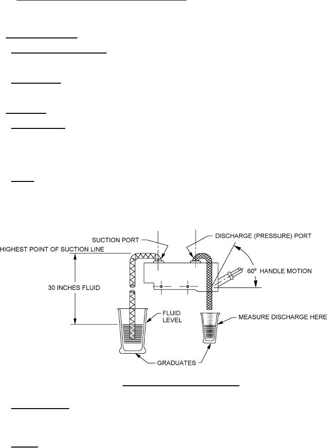
4.6.2 Priming. The pump shall be mounted in the normal operating position with line (size as specified in the
applicable standard) connecting the suction port to the hydraulic fluid supply. The fluid level shall not be less than 30
inches below the suction port, as specified on figure 1. Operate pump at a rate of not less than 20 strokes per minute
to determine the pumping cycles necessary to produce flow.
FIGURE 1. Hand pump priming and flow test set-up.
4.6.3 Ability to hold prime. Mount pump and tube as specified in priming test (see 4.6.2) and completely prime the
pump, overflowing fluid through the pump discharge port to the atmosphere. After pumping is stopped and allowing
not less than 30 minutes, determine leakage from the pump and suction line (see 3.6.3). Ambient and fluid
temperatures shall not vary more than 2°F (-17°C) during this test.
4.6.4 Pressure.
6
For Parts Inquires call Parts Hangar, Inc (727) 493-0744
© Copyright 2015 Integrated Publishing, Inc.
A Service Disabled Veteran Owned Small Business