MIL-P-24475 (SHIPS)
The following curves shall be provided:
3.7 Performance curves.
(a) Head versus flow.
(b) Hydraulic efficiency versus flow.
(c) Net positive suction head required under normal, maximum and minimum
operating conditons.
(d) Brake hp. versus flow.
A brief discussion of the following design features shall
3.7.1 Design features.
be provided
Those areas in which system design conditions. as furnished by the procuring
(a)
agency (Government or shipbuilder) , adversely affect pump reliability or
result in abnormal design features.
Steps required for disassembly and reassembly (including alignment) to per-
(b)
form routine maintenance.
(c)
Any other design features which the manufacturer considers of siqnificant
interest to describe the proposed unit.
The galvanic compatibility of the materials used for parts in contact with
(d)
the pumped fluid.
3.7.2 Use of materials other than as specified herein shall be justified. It is not
intended that materials which conform to and are used as specified herein shall require
justification.
3.7.3 Calculations shall be submitted to cover the following
Shafting analysis of pump and driver assembly including calculation of
(a)
critical speed. If calculations are done by a computer, results need only
be submitted. The following shall form the basis of the critical speed
calculation
(1) The effects of all major changes in shaft cross section moment of inertia
shall be included.
(2) No support for the shaft shall be assumed other than at the desinated
bearings.
(3) All masses in the rotating system, including the effect of entrained
fluids , shall be lumped at discrete points along the shaft.
(4) No support for any shafting shall be assumed to be provided by additional
shafting when two sections of shafting are separated by a flexible
coupling, nor should any flexibility in bending or shear be assumed
for a rigid coupling.
Loads imposed on the bearings. The calculations shall include the following:
(b)
(1) Axial and radial loads and load directions. Loading should be calculated
for the design point and also for the highest loaded conditions over the
operating range. These loads shall include all operating loads together
with those that might be induced by thermal expansion and by build-up
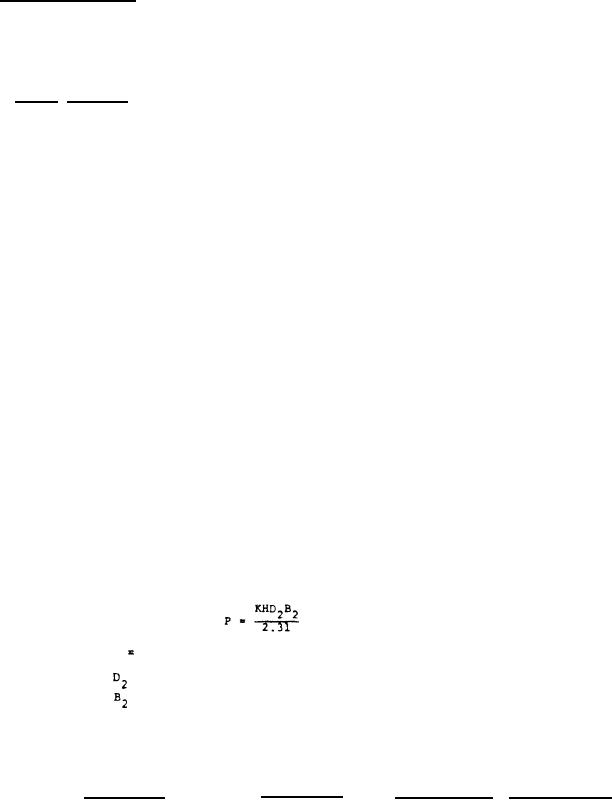
of tolerances in the completed assembly. The radial loads at the im-
peller may be calculated by the following:
Where:
P
the radial load in pounds.
H = head in feet.
= impeller outside diameter, inches.
= repeller overall width including shroud, inches.
K = a constant which varies with capacity.
Unless data, supported by tests, justified the selection of a lower
value, K shall be assumed in accordance with the following:
At 140 percent
At rated flow
At shut off
rated flow
Casing type
0.00024Ns
Single volute
less than 1500
0.10
0.36
0.36 for Ns of
1500 or greater
12
For Parts Inquires call Parts Hangar, Inc (727) 493-0744
© Copyright 2015 Integrated Publishing, Inc.
A Service Disabled Veteran Owned Small Business