MIL-P-17881D(SHIPS)
3.3.2.4 The requirements specified in 3.3.2.4.1 through 3.3.2.4.5 shall apply to
casings of type I and type II pumps.
3.3.2.4.1 The casings shall be divided into two parts so as to permit ready removal
of the rotors and for bearing and gland replacement.
3.3.2.4.2 The design of casings shall be sufficiently rugged to withstand without
fracture or appreciable distortion the strains to which they may be subjected.
3.3.2.4.3 Clearance shall be provided around bolt heads and nuts to permit the use
of ordinary tools.
3.3.2.4,4 Fitted bolts or heavy dowel pins shall be provided to insure maintenance
#
of alignment of casing halves in reassembly. Tapered dowel pins shall be corrosion-resistant,
shall have a threaded end and nut design, and shall be secured against coming adrift under
shock loading.
3.3.2.4.5 Forcing bolts shall be provided for breaking joints.
3.3.2.5 The outer casing of type III and type IV pumps shall be a solid barrel suffi-
#
ciently rugged to withstand, without fracture or distortion, the strains to which it may be
subjected.
3.3.3 Suction and discharge connections. The suction and discharge connections shall
#
be flanged in accordance with MIL-STD-438 for submarines, MIL-STD-777 for surface ships, or
as otherwise specified (see 6.1). Suction and discharge connection sizes, orientation?
location and surface finish shall be as specified (see 6.1).
3.3.4 Impellers.
3.3.4.1 Outside surfaces of impellers shall be smooth finished.
3.3.4.2 Impellers shall be keyed on the shaft and securely held against lateral move-
#
ment by locked nuts or other means approved by the design review agency.
.
3.3.4.3 Each impeller shall be dynamically balanced.
3.3.4.40 Impellers shall not be fitted with wearing rings. The impeller hub wearing "
surfaces shall have material thickness to permit reducing the diameter of the impeller hubs
by as mush as 0.050 inch to accommodate undersize easing wearing rings to restore design
running clearances.
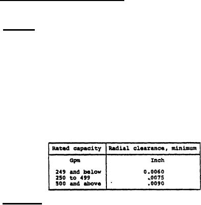
3.3.4.5 The radial clearance between impeller hub wearing surfaces and the casing
wearing rings shall be not less than that specified in table I. All clearances to be
measured on the radius; that is, the difference in diameter between wearing surfaces shall
be not less than twice the clearance in table I.
Table I - Radial clearance
3.3.5 Pump shafts.
3.3.5.1 All shaft threading, except threading for rolling contact bearing locknuts,
shall be counter to the direction of rotation. Shaft threading for rolling contact bear-
ing locknuts may be clockwise or counterclockwise.
3.3.5.2 Bearing locknuts shall be provided with a positive means of locking.
3.3.5.3 Shafts shall be fitted with shaft sleeves in way of stuffing box, diaphragm
#
bushings and water lubricated bearings. A flinger shall be so located that leakage which
sight occur between the stuffing box shaft sleeve and the shaft, as well as from the stuff-
ing box, is not allowed to reach pump or motor ball bearings.
5
For Parts Inquires call Parts Hangar, Inc (727) 493-0744
© Copyright 2015 Integrated Publishing, Inc.
A Service Disabled Veteran Owned Small Business